Dead-front · ITO capacitive touch · Membrane switches
Custom Dead-Front Panels & ITO Capacitive Touch Sensors for Smart Appliances
Elevate your appliance HMI with seamless dead-front effects and reliable touch control. Built to withstand moisture, steam, and rigorous appliance-grade testing.
Send a drawing, a 3D file or a photo of your current panel. Written engineering feedback within 48 business hours -- no obligation, NDA on request.


- 0.3 mm
- Minimum trace width — 0.4 mm pitch, 0.85 mm edge clearance
- 80–150 Ω/□
- In-house ITO printing — sheet resistance held in series production
- ≥80% / ≤7%
- Transmittance / haze across a clear display window
- <150 ms
- Key response, 9.5 mm actuator · <5 ms per key scan
- ≥10 MΩ
- Insulation resistance at DC 100 V, 1 minute
- −10…+60 °C
- Operating range at RH ≤ 90%, storage −20…+70 °C
Typical production values, taken from a released appliance program specification and desensitised. Values for your part are agreed in the qualification plan and verified under the conditions defined there.
Product range
Five ways to build a front panel — usually combined
Most programs do not buy one of these. They buy a membrane keypad with a printed front, or a capacitive sensor behind a dead-front window with an edge-lit guide underneath. The list below is how the part is quoted, not how it is shipped.
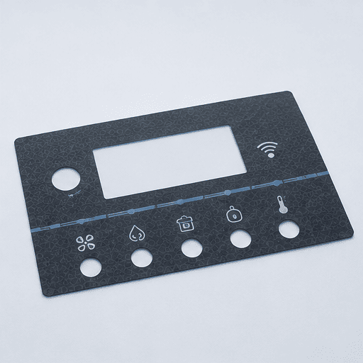
MEMBRANE SWITCHES
Membrane Switches & Keypads
Printed silver-circuit keypads with tactile domes or non-tactile travel, built as a single laminated part with your decorative front. Rigid or flexible tails, ZIF or connector termination.
PET / PC overlays · embossed or flat keys · silver or carbon traces · ZIF tail 0.5 / 1.0 mm pitch
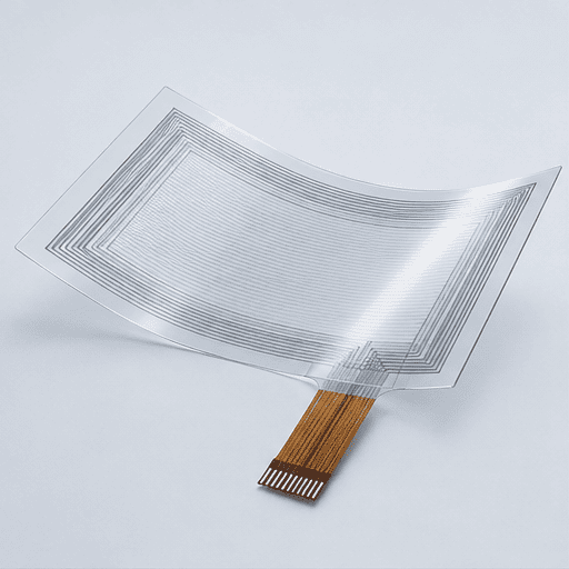
ITO CAPACITIVE TOUCH
ITO Capacitive Touch Sensor Films & Panels
Single- and double-sided ITO sensor films, patterned, cleaned and printed on our own lines rather than bought in — self- or mutual-capacitance, laid out around your controller and your mechanical envelope. Supplied as bare sensor film or laminated behind the finished front panel.
ITO on PET · 80–150 Ω/□ · single/double-sided · sensing through 1–4 mm glass or plastic
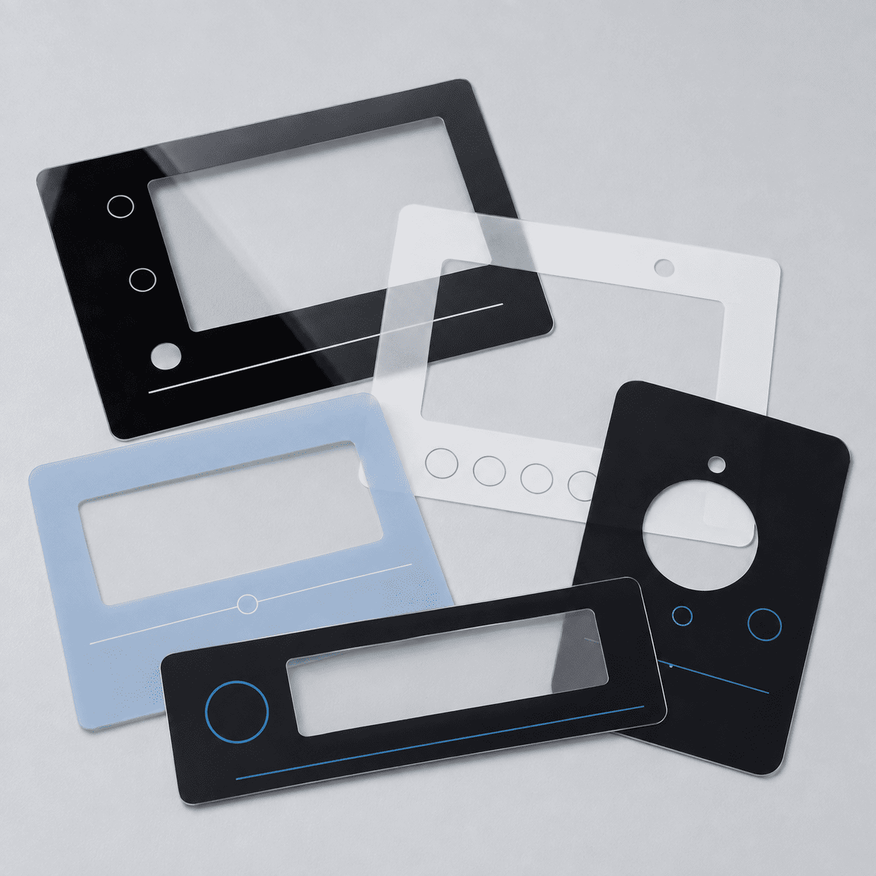
DECORATION
Printed Graphic Overlays
Colour-matched front panels in gloss, matte, textured or metallic finishes, with selective transparency, hairlines and window cut-outs printed in register.
Roll-to-roll colour printing · CCD registration · hard-coat, anti-glare or anti-fingerprint
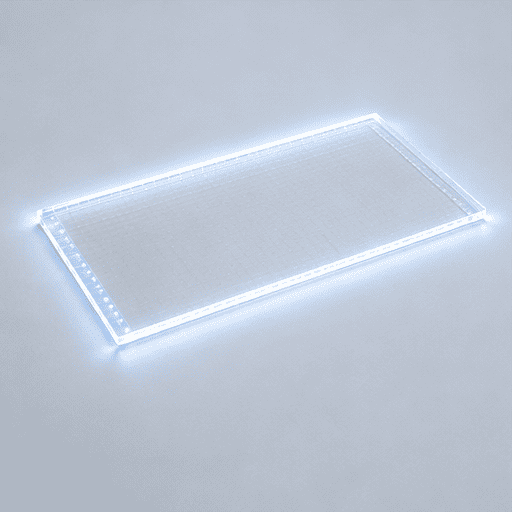
OPTICS
Light Guide Films & Backlight Modules
Edge-lit light guides and diffuser stacks laminated into the panel, so icons and rings light evenly from a small number of LEDs instead of one LED per symbol.
Micro-dot light guides · diffuser + reflector stack · edge-lit LED bar · single or multi-colour zones
INTEGRATION
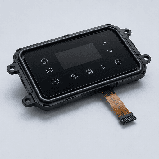
Integrated HMI Panel Assemblies
Sensor, graphics, optics, waterproof barrier and carrier bonded into one part you can fit to your PCB on the line — fewer suppliers, one dimensional tolerance chain, one RMA owner.
OCA / LOCA bonding · gasket and sealing structure · acrylic or ABS carrier · FPC or connector out
Dead-front panels
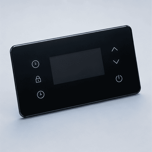
A surface that shows only what matters right now
A dead-front panel reads as one uninterrupted surface when the appliance is off, and reveals only the controls relevant to the current mode when it is on. It removes the permanently printed legend clutter that dates a product, and it lets one physical panel serve several model variants.
It only works if three things are designed together: how opaque the black layer is, how evenly the guide lights the icon, and where the sensor pad sits relative to both. Buying them from three suppliers is where most dead-front projects go wrong.
- Opacity
- Light-blocking ink tuned so the icon is invisible when off and still bright enough when lit — the whole effect lives in this one window.
- Uniformity
- Micro-dot light guide patterns designed per icon, so a symbol does not show a hotspot above the LED and a dim corner away from it.
- Sensing
- Sensor pads aligned to the visible icon, not to the mechanical grid, so the touch target and the lit target are the same place.
Light guides & backlighting
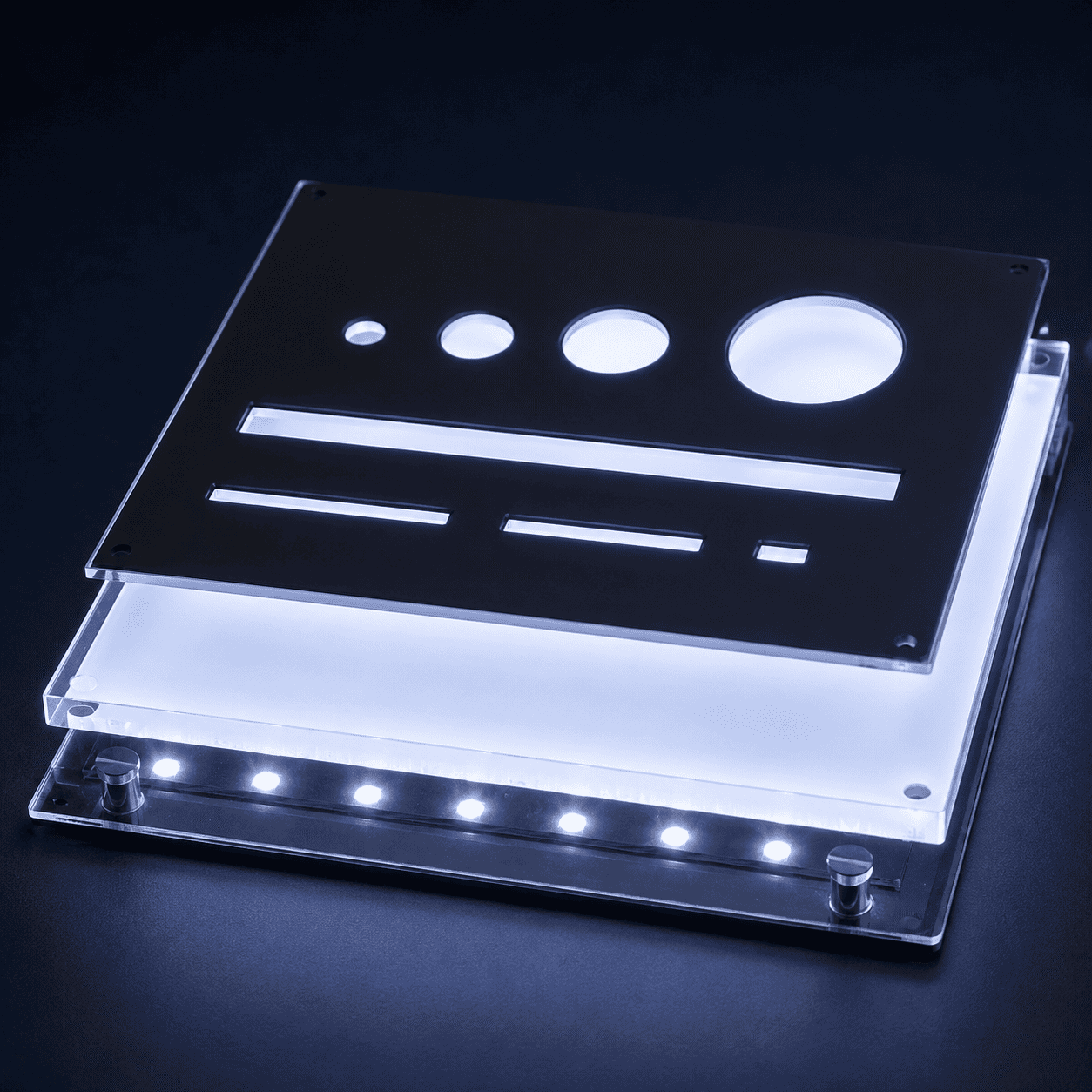
Even icon lighting without one LED per symbol
Edge-lit guides with micro-dot extraction patterns spread light from a small LED bar across the whole icon field. Fewer LEDs means lower current draw, fewer solder joints on your board and less binning variation between units on the same shelf.
- Stack
- Light guide, diffuser and reflector laminated into the panel, not assembled around it.
- Zones
- Independently lit regions for mode groups, status rings or progress indication.
- Colour
- Single-colour or multi-colour zones, matched to the ink so off-state colour stays neutral.
Construction
What is actually inside the panel
A released appliance panel we build runs to fifteen laminated layers. Grouped by function, they come down to ten decisions — and almost every field failure traces back to one of them being made by a different supplier than the ones above and below it.
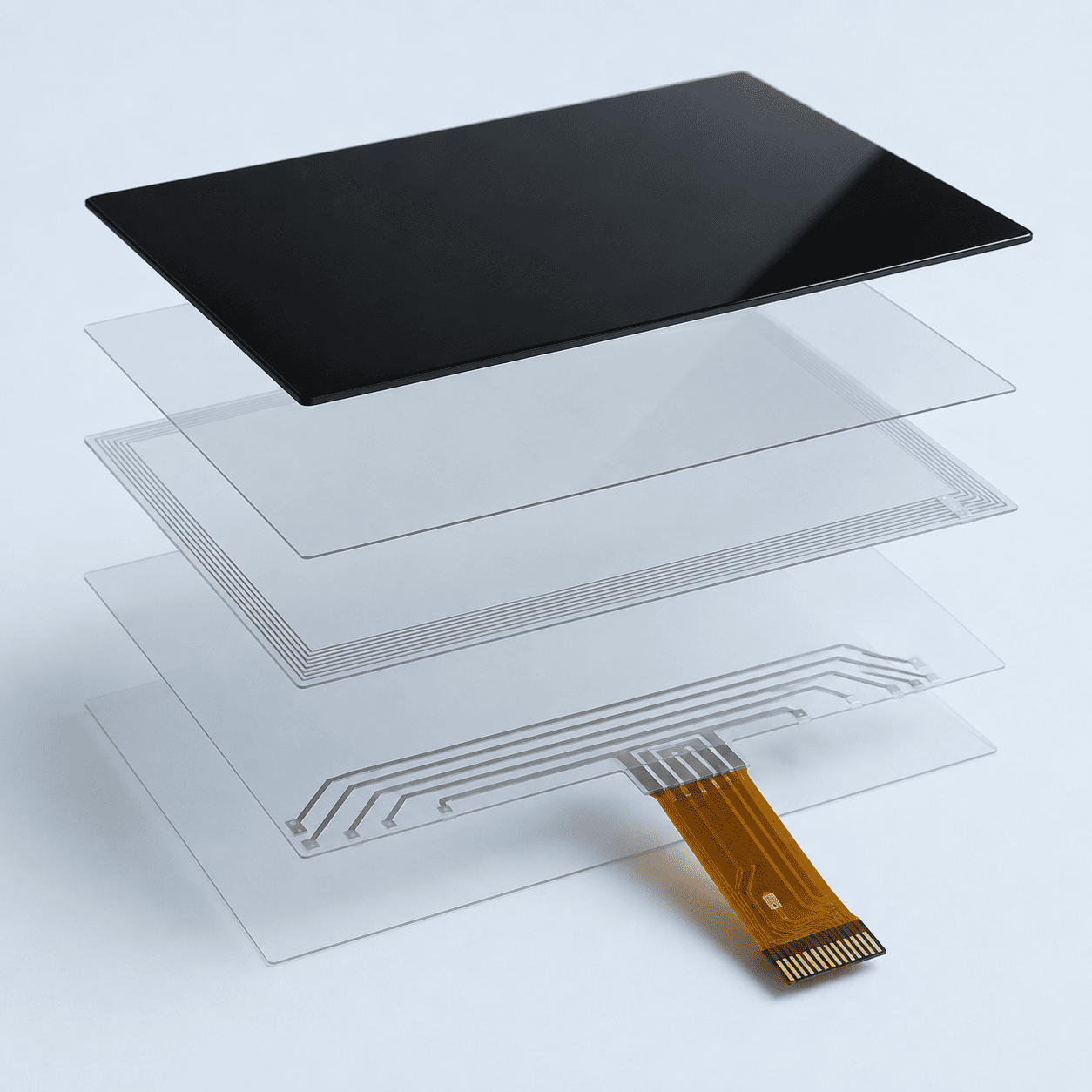
- 01Peel tab and release liner for line handling
- 02Hard-coated PET or PC graphic substrate
- 03Printed colour, icon and hairline layer
- 04Optically clear adhesive
- 05Sensor substrate — ITO or metal mesh
- 06Silver bus and conductive trace layer
- 07Dielectric insulation layer
- 08Light-blocking black ink
- 09Waterproof barrier film
- 10Stiffener, foam and FPC tail
Specifications
The numbers your engineers will ask for first
Published so you can rule us in or out before the first call. Every line is a value we hold in series production on released appliance programs, with the condition it is measured under.
| Parameter | Value | Condition |
|---|---|---|
| Minimum trace width | 0.3 mm | Silver paste, screen printed |
| Minimum trace pitch | 0.4 mm | Adjacent conductor spacing |
| Minimum edge clearance | 0.85 mm | Conductor to panel edge |
| ITO sheet resistance | 80–150 Ω/□ | Four-point probe, incoming and in-process |
| Transmittance, clear window | ≥ 80% | Full-transparency area |
| Haze, clear window | ≤ 7% | Full-transparency area |
| Transmittance, white icon area | > 38% | Printed white legend |
| Key response time | ≤ 150 ms | 9.5 mm brass actuator |
| Key scan time | < 5 ms per key | Controller-side measurement |
| Insulation resistance | ≥ 10 MΩ | DC 100 V, 1 minute |
| Adhesive bond strength | > 10 N | Measured at 20 min and at 168 h |
| Operating temperature | −10 … +60 °C | RH ≤ 90%, non-condensing |
| Storage temperature | −20 … +70 °C | Packaged |
| Sampling / inspection | GB/T 2828.1 | AQL agreed per program |
These are capability figures, not a blanket guarantee for every geometry. Tight combinations — minimum trace width across a large panel, or maximum transmittance with full opacity when off — are confirmed on your specific artwork during the DFM review and fixed in the qualification plan.
Applications
Where these panels have to survive
The circuit is rarely what fails. Condensation, heat ageing, cleaning agents and adhesive creep are — which is why the environment drives the stack-up more than the key count does.
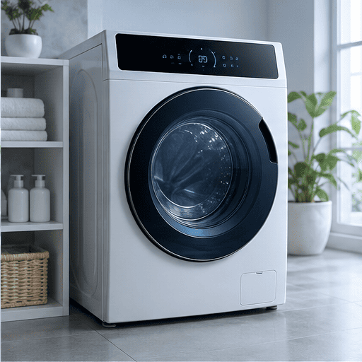
Washing machines & dryers
Long cycle-selection arrays behind a sealed front, where detergent, steam and repeated wipe-downs attack the panel more than the user does.
SEALED FRONT · DEAD-FRONT LEGEND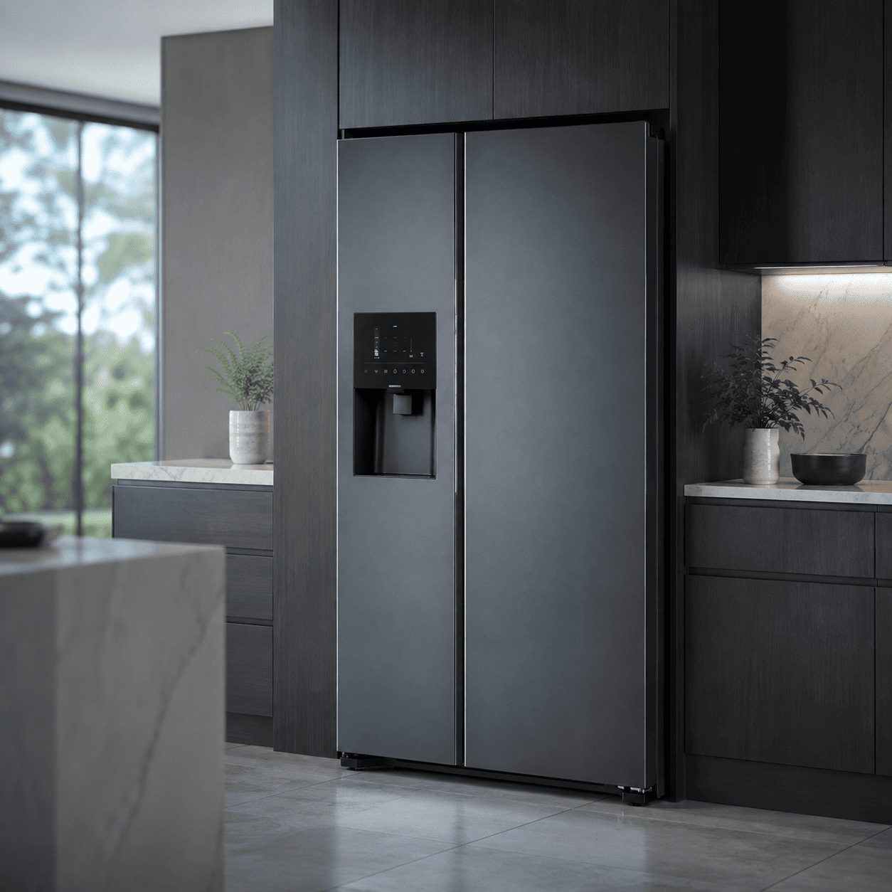
Refrigeration & freezers
Door-mounted panels that must stay readable and responsive through condensation cycles and cold-side temperature swings.
CONDENSATION · COLD START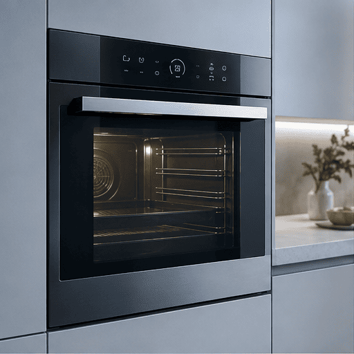
Cooking & built-in ovens
Panels working next to a heat source, where adhesive creep and ink shift show up long before the circuit fails.
HEAT AGEING · GLASS BONDING
Small domestic appliances
Compact, cost-sensitive interfaces where a single integrated part usually beats an overlay plus a separate sensor plus a light pipe.
PART COUNT · UNIT COST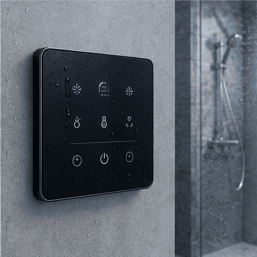
Bathroom & water heaters
Wet-environment panels: standing water, steam and cleaning agents, with a sealing structure designed into the laminate rather than added around it.
WATER INGRESS · SEALING
Industrial & commercial equipment
Lower-volume, longer-life programs — chemical resistance, glove operation and long-term parts availability matter more than unit price.
GLOVE USE · LONG LIFECYCLEManufacturing
Printing, forming and testing under one roof
10,000 m² in Suzhou, of which 8,000 m² is Class 100,000 cleanroom. Decoration, circuit printing, lamination, die cutting and functional test all sit in the same flow, so a stack-up change does not become a four-supplier negotiation.
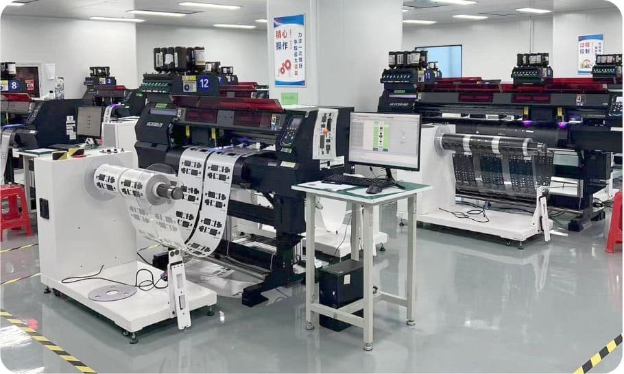
Colour printing
Roll-fed decorative printing with inline inspection, so colour and register are controlled on the web rather than corrected after cutting.
- 18 roll-fed colour printers
- 2 CCD high-speed colour lines
- Inline colour management
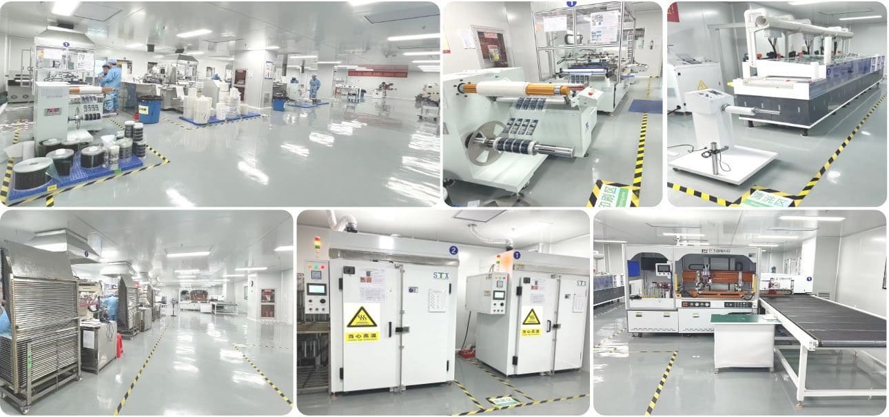
Circuit & graphic printing
Silver and dielectric printing on ITO and PET, with cleaning and curing held inside the cleanroom.
- 9 CCD roll-to-roll lines
- 2 CCD sheet-fed lines
- ITO cleaning line
- 2 sheet curing ovens
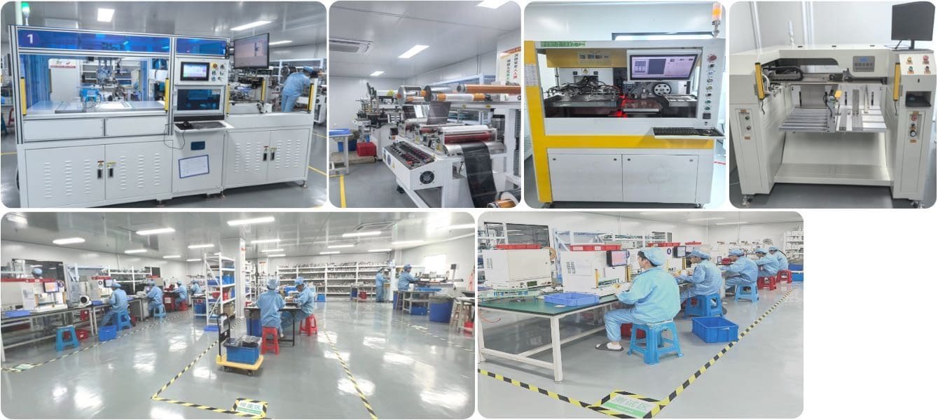
Forming, lamination & assembly
Die cutting, embossing, bonding and final assembly, with functional test stations built into the flow rather than bolted on at the end.
- 1 CCD auto die-cutting line
- 2 roll die cutters
- 2 auto lamination lines
- 6 functional test lines
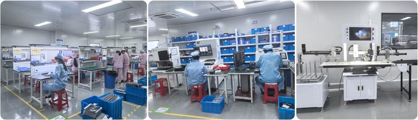
Inspection & reliability
AOI plus manual inspection on the line, and a separate reliability lab for the tests that decide whether a design survives its warranty.
- 3 AOI vision systems
- 18 manual inspection stations
- 2.5D measurement
- Thermal shock chamber
Floor area, equipment counts and headcount are company-reported figures from our 2025 capability profile. Photographs are of our own facility. A current equipment list and an audit slot are available on request.
Engineering support
Engineers who will actually read your drawing
The review you get back does not come from a sales inbox. It comes from the engineers who lay out the sensor, choose the stack-up and sign off the first article — and you can keep talking to them once the program is running.


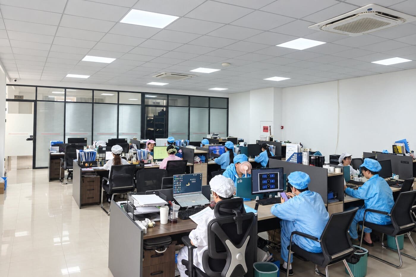
- 20+
- Design, process and quality engineers on staff — the people your drawing actually reaches.
- In English
- Technical correspondence direct with the engineer who reviewed your part, not a sales template.
- NDA first
- Signed before drawings are exchanged, as standard. No customer name, logo or program is ever published.
Quality & documentation
Tested in-house, documented to your format
Reliability testing happens on site rather than at a third-party lab on a two-week queue, so a failed sample turns into a design change in days. The equipment below is what the qualification plan draws on.
- Transmittance / haze meter
- Four-point probe sheet-resistance meter
- Low-resistance meter
- Dielectric withstand tester
- Boiling-water immersion chamber
- Peel and pull-off strength tester
- Salt-spray chamber
- 2.5D measuring system
- Thermal shock chamber
- Temperature & humidity cycling chamber
As a component supplier we do not certify your appliance. We support OEM qualification with RoHS and REACH material declarations, reliability test reports and the documentation required for your own CE file. Sampling and inspection follow GB/T 2828.1 at an AQL agreed per program.
How we start
From a rough drawing to series supply
The first step costs you nothing and takes less than two days. Most of what we find there is cheaper to change before tooling than after.
Send the part
A 2D drawing, a 3D step file, a photo of the current panel or a competitor sample. Sketches are fine — most first submissions are.
Free DFM review
Within 48 business hours you get written feedback on trace routing, stack-up, sealing and the two or three details that usually push tooling cost up.
Samples & reliability
Prototype tooling and first samples, then the reliability sequence agreed in the qualification plan, with the test report.
Ramp & supply
Production tooling, PPAP-style documentation to your format, then series supply with the agreed AQL and change-control rules.
Questions we get before the first order
Frequently asked
Do you make membrane switches, capacitive panels, or both?
Both, and frequently in the same part. A single panel may carry a tactile membrane keypad on one side and a capacitive zone on the other, sharing one printed front and one tail. If you are deciding between the two technologies, that is exactly what the free DFM review is for.
What is a dead-front panel and when is it worth it?
A dead-front panel looks like a plain surface when it is off and only shows the icons that are currently relevant when it is lit. It is worth it when the interface has many modes and you do not want to print every legend permanently, or when the industrial design calls for an uninterrupted surface. It requires the black layer, the light guide and the sensor to be co-designed, which is why it is usually bought as one assembly.
What is the minimum order quantity?
Prototypes are built in tens. Series MOQ depends on tooling and on how the panel nests on the web — we quote it with the DFM feedback rather than as a fixed number, because a small layout change often moves it substantially.
Can you work from our existing panel instead of a drawing?
Yes. Send a sample or clear photographs with overall dimensions and we will reconstruct the stack-up and come back with what we can match, what we would change and why.
Do you supply the controller or firmware?
No. We build the front-end: sensor, graphics, optics, sealing and carrier, ready to integrate with your control electronics. We will work to your controller's sensing requirements and share the sensor data your firmware team needs, but the board, the firmware and the system-level compliance stay with you.
What about CE, RoHS and REACH?
As a component supplier we do not certify your appliance. We supply RoHS and REACH material declarations, reliability test reports and the documentation your qualification process needs to carry the part through your own CE file.
How do you protect our design?
NDA before drawings are exchanged, as standard. We do not publish customer names, logos or programs — which is why every example on this site is desensitised.
Where do you ship and how long does it take?
We ship worldwide from Suzhou, China. Prototype lead time is typically two to three weeks after drawing freeze; series lead time is agreed per program along with the forecast and safety-stock arrangement.
Free DFM review
Send us the part. We will tell you what we would change.
Drawings, a 3D file, a photo of your current panel or a competitor sample — whatever you have. Written engineering feedback within 48 business hours, from an engineer, not a sales template.
- 01Stack-up and sealing review against your environment and cleaning regime
- 02Trace routing and sensor layout checked against your controller
- 03The two or three details that usually drive tooling cost, flagged early
- 04Indicative lead time and volume breaks, with no obligation